This section contains a lot of theory and basic information. The information is important to understand how Wi-Fi works.
Wireless Wi-Fi networks work by radio. All Wi-Fi enabled devices have an antenna by which they can send and receive radio signals.
We will kick off this section by discussing radio waves and a little bit about how radio communication works.
About radio waves
Radio signals are transmitted by an antenna with a certain output signal strength or effect as it is called. As the radio signal is spreading out from the antenna it becomes weaker and weaker the further away from the sender it gets. Eventually, the signal strength is so weak that the signal can no longer be understood by a receiver. This is similar to how you cannot hear somebody from too far away because the sound is weakened and spreads out with distance. The further sound waves travel the weaker they become.
There are many reasons for the weakening of the radio signal. Here are a few examples:
- As the signal is spreading out the effect of the signal is also spread out over a bigger area. Much like if you throw a pebble in a pond the height of the waves decreases the further out from the impact that the waves spread. The energy of the pebble’s impact which transferred to the water has to spread out over a bigger and bigger area the further the waves travel
- Absorption, that the effect or energy of the signal is simply absorbed by the air itself, the water in the air, particles or other things so that the energy of the signal is lost
- Scattering, that the signal is split up after colliding with particles, objects or edges. One example of scattering includes how a rainbow can be created when light is split up into different wavelengths after hitting water droplets in the air
Radio signals are electromagnetic signals just like light. And similar to light, radio signals can be reflected by or bounce on things. This can be both positive and negative depending on the circumstances. In a small home it might not matter much if radio signals bounce around a bit, and sometimes it can even be beneficial, but other times it can be a bother for the communication.
A radio wave can act much like regular waves in the ocean. If two waves meet up and their crests and troughs line up then they will form a new much bigger wave, much bigger than the individual waves were.
If two waves meet up and the troughs of one wave line up with the crests of the other wave then the two waves will cancel each other out. If there’s a perfect match between the two waves for both their wave heights and their wavelengths then they could cancel each other out more or less completely.
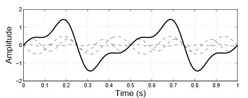
Radio Waves act in the same way. Two radio waves that meet up will interact with each other to increase and decrease the signal strength. In the following picture we can see two radio waves (dashed lines) with different wavelengths and wave heights (amplitude) that meet up, and together they form a new combined radio wave (solid line) that appear very different to the original radio waves.
Even if you just have a single radio transmitter the radio waves are spreading out in all directions and will bounce around the room. Basically, everything you see around you is something that radio waves can interact with by being reflected, diffracted or scattered. Extremely simplified you could say that radio waves pass through softer materials easier and are reflected against harder surfaces. The result is that the air is filled with radio signals bouncing around in all directions. So even with a single transmitter sending out a single signal you could still get interference between the radio signals that are bouncing around.
Imagine putting a Wi-Fi router in the room you are in. When the radio signal encounters walls, furniture, ceiling and all other things the radio signal will be affected by the materials it encounters. Some of the signal effect will pass through the items, some is absorbed and some of it will reflect to bounce back into the room. This happens on every surface you see, so the room is literally filled with bouncing radio signals.
The bouncing signals are often much weaker than the original signal directly from the antenna since not all of the signal will be reflected. If you were to put the Wi-Fi router right next to a concrete wall or steel plate then a lot of the signals would bounce on the hard surface right after leaving the antenna, and the bouncing signal is still strong enough to definitely interfere the antenna signals considerably.
You always get the strongest signal strength with the best signal quality if you have a completely free line of sight to the antenna of the Wi-Fi router. Anything that is blocking the signal will always affect it in some way. For that reason, it is always absolutely best to place a Wi-Fi router in an open space with a free line of sight to as many places that you want to cover with your Wi-Fi signal as possible.
If instead you were to place your Wi-Fi router in a closet, under a desk or in a box in the hallway then you’ve already ruined any chances of achieving perfect radio signal quality. You could still end up with a wireless network that works well enough, but it will be considerably worse than if you would move the Wi-Fi router to an open space.
About antennas and radiation patterns
A radio antenna can have different appearances depending on what purpose it is designed to fulfil. Antennas also have a different length depending on what wavelength that they are made to transmit and receive radio waves on.
Antennas are manufactured to radiate radio waves in different patterns. The manufacturing process and the design of the antenna can control in which particular directions (if any) that the antenna should focus its radio wave emissions.
The most extreme example is parabolic antennas, where the whole antenna is built to send (or receive, or both) as much of its effect as possible in one single narrow beam. This design concentrates all of the energy of the radio transmission in one single direction. Parabolic antennas are used for longer distance communication where you have another single antenna far away that you want to establish communication with.
But there are also many other variations on so-called directional antennas that direct radio waves in one or several directions.
The absolutely most common type of antenna for Wi-Fi routers and home networks is the dipole antenna which has an omnidirectional radiation pattern. Such an antenna will be more or less equally powerful in all directions, which is what you usually want in a home network environment. Also, the manufacturer couldn’t know what type of antenna that you would otherwise require in your particular home, so they always default to including omnidirectional antennas.
This is another reason for why you should place your Wi-Fi router in an open area of your house. The router will radiate radio waves more or less equally in all directions. If you place your router in a corner then some of that radio effect will enter the walls and be absorbed right away without producing any positive results for your Wi-Fi network.
Many routers are equipped with internal Wi-Fi antennas with a particular antenna alignment, and the router is then meant to be placed in a particular way for the antenna to have the correct alignment. You should always look at the instructions manual for your router and place it in the correct way standing up or lying down. Otherwise, the radio communication won’t be working under optimal conditions.
If the router has an external antenna that can be set in different angles, then you can often choose how you want to place your router, and then pick an angle for the antennas. Often the manual for the product will have instructions for antenna alignment. Basically, it is best if the antenna alignment of the Wi-Fi router matches up with the antenna alignment of the devices that you want to connect to the Wi-Fi router.
Matching antenna alignment is not always as straightforward as one might think. Most devices have built-in antennas that you can’t see, so you don’t know what alignment they have. You can’t look at a mobile phone and see what antenna alignment it has got. Also, how will you hold your mobile phone when you are using it? If it is lying down then the antenna is lying down. If you hold it straight up then the antenna is upright. Or perhaps sideways. Luckily a phone rarely needs a high-speed Wi-Fi connection so you will often get away with phone Wi-Fi quality.
But look at your laptop instead. The antenna is often integrated into the screen and is upright when you are using the laptop, but not always. For example, a lot of MacBooks have their antennas integrated into the screen hinge, lying down.
If you have multiple antennas on your router you could face some of them straight up and others lying down.But once again whether or not this is beneficial depends on the type of router you have and what capabilities it supports. Many manufacturers recommend angling the antennas. For three antennas you would have the middle antenna somewhat straight up, and then angle the two side antennas 45-60 degrees. But check with the router manual to see what their recommendation is for your particular home router.
Radio channels, an introduction
If you’ve ever listened to the radio then you know that there are different radio channels you can tune in to such as Kiss FM, AMP or Now FM.
Then you probably also know that those radio channels are operating on different Frequencies that they are allowed to transmit on. Different countries have different governing bodies that rule on how the radio frequencies can be used. In the USA, for example, the Federal Communications Commission (FCC) regulates radio communication, including who can use which radio frequencies for transmitting FM radio.
This is necessary because if two channels were to transmit on the same frequency within range of each other then they would disturb one another. There must also be some unused frequency space between the channels. This is because radio signals are never transmitted just on an exact frequency such as 99.3MHz. The signals are actually “smeared out” over a little range of frequencies surrounding a center frequency. This is called the channel width.
So if a radio channel is transmitting on the frequency 99.3MHz, then it is really just the center frequency which is 99.3MHz, but the radio signals can also be heard over the nearby frequencies such as 99.2MHz or 99.4MHz. You can even hear this effect if you have an old radio available. When you tune in a channel you can hear how the channel first appears with some distortions as you close in on the right frequency, and then as you get right on top of the center frequency you get perfect sound quality.
| The frequency is simply explained how long or short the wavelength of the radio signal is, which affects how many times per second the wave swings up and down or oscillates. With higher frequencies the wave oscillates more often and the wavelength is also shorter. Lower frequencies mean fewer oscillations of the wave per second and the wavelength becomes longer.
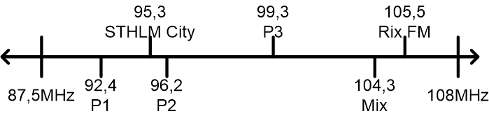
When you listen to the radio in your car or kitchen you often listen to the so called FM band of radio frequencies between about 87.5 – 108 MHz. One Hertz (Hz) means one oscillation per second (one wavelength). MHz stands for Mega Hertz – million oscillations per second. |
But let’s say that a radio channel is transmitting in the Stockholm area on the frequency 96.5MHz.
Then nobody else can transmit a radio signal on 96.5MHz there because the radio signals would disturb each other. But how far away do you have to be to put up another transmitter on 96.5MHz without causing disturbances? The simple answer is that it depends on how strong the radio transmitter is, or which effect it has, and also on what type of antenna that is used and how that antenna focuses the radio transmission. The important bit is that if two radio senders use the same frequency then their radio waves will disturb each other if they are within range of each other and their transmissions overlap.
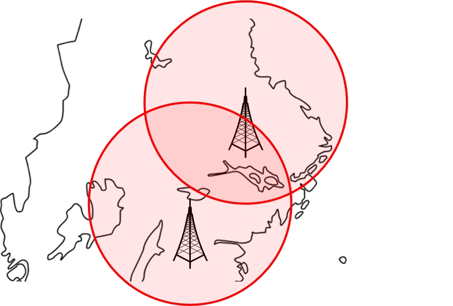
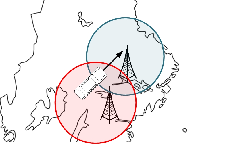
So as long as two transmitters send on the same frequency their signals will disturb each other if they overlap each other’s coverage areas. In the picture below the two radio towers are sending on the same frequency, and there is a huge overlap in the middle of their signals. That whole overlapping area is then affected by the disturbances, so it will be very difficult in that overlapping area to listen to the radio signal that either tower is transmitting.
The frequency 96.5MHz can be used at many different places simultaneously. The important thing is that the transmitters are not within reach of each other.
But like we stated earlier the radio signals are only centered on a frequency. In reality, the signals are transmitted over a range of frequencies. How much the signals are smeared out over that frequency range depends on the exact technology that is being used to transmit the signal. For radio on the FM band signals are often about 100kHz “wide”, for example from 96.45MHz up to 96.55MHz. Or from 105.4MHz to 105.5MHz. It is usually not allowed to use frequencies even close to those of other radio channels. Instead, the radio channels that FCC and other governing bodies hand out are well distributed with enough gaps between the different radio channels so that they do not disturb each other.
As long as you just have a single transmitter you won’t have any issues. The problem will always arise when you want to cover a larger area with multiple transmitters that should transmit simultaneously for extended coverage, but you don’t want the transmitters to disrupt each other.
That’s when the puzzle of radio channels begins!
A puzzle of channels and transmitters
Each radio transmitter on the FM frequency band has a reach ranging from that of a city, or sometimes a county or even somewhat bigger areas.
But the further the distance from the transmitter the weaker the signal gets, and eventually the signal is weak enough that you cannot listen to it without also hearing disturbances. That’s when you have to put up another transmitter to increase the total coverage area. The new transmitter must be close enough to the first one so that the radio signals overlap. Otherwise, you couldn’t go in your car between the two areas without losing the signal. So the signals must overlap.
The puzzle is in the fact that the two transmitters must send out the same radio show, but they must use two different frequencies so that they can overlap and be within range of each other without disturbing each other by transmitting on the same radio frequency.
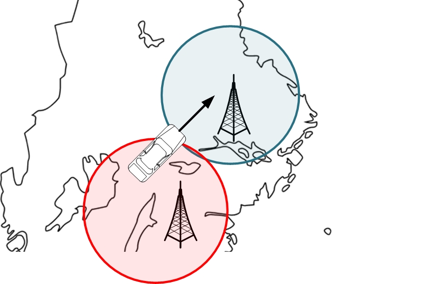
The two transmitters in the picture above are far away from each other. When going by car from one transmitter to the next, you will probably cross areas with bad coverage where of the transmitters have a good enough signal. To solve this problem the senders must be closer together, or the effect of the senders could be increased so that each sender gets a farther reach.
In the picture above the senders have been moved closer to each other, which means that the overlapping area between the two senders is bigger. Then it gets much easier to ensure that the overlap between the senders is big enough so that you always have a good signal from at least one of the towers when you go from one area to the next.
The transmitters above are using different frequencies to broadcast the same radio show. Car stereos handle this automatically these days by moving between frequencies without you noticing.
The puzzle I mentioned starts when you want to cover a big area and you also have many radio shows that you want to transmit simultaneously. Let’s say each transmitter needs to broadcast 10 radio shows. That means each transmitter will work on 10 different frequencies, and none of the channel frequencies must collide with any other channel frequencies on any other radio tower within range. Then you have a much more challenging puzzle that requires planning from someone who can control exactly what frequency that is used for which show in what area. Without that control, it would be up to each individual company to coordinate their radio usage with every other company. For North America, there are more than 9000 radio channels that would have to coordinate how they transmit their programs, which would quickly become an impossible task.
Here we have drawn up a simplified radio frequency planning puzzle. In this picture, each radio tower only transmits on a single frequency. Each frequency is represented by a unique color. What we need to do is two things:
- We need to cover the whole area, so there must be no place on the map that is not covered by at least one radio tower
- None of the towers must transmit on a frequency that overlaps with another tower within reach that sends on the same frequency
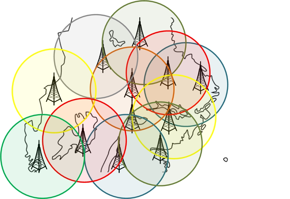
In the picture above we have succeeded since the whole map is covered and no same-color circles are overlapping.
|
Previous part: |